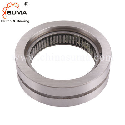
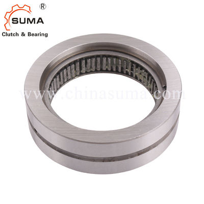
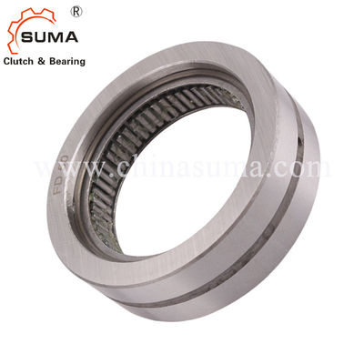
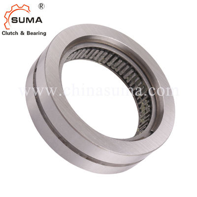
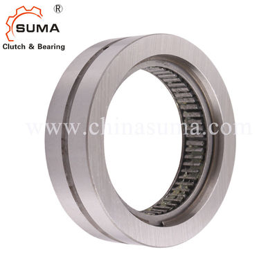
FD12 1 Directional Backstop Freewheel Sprag Type Clutch
Features
Internal Freewheels FD are sprag freewheels without an inner ring. The customer s hardened and ground shaft is used as the inner track.
The freewheels FD are used as:
➧Backstops
➧Overrunning Clutches ➧Indexing Freewheels
The standard type and type with P-grinding for increased service life and indexing accuracy do not have bearing support. In the case of the standard type, every second sprag has been be replaced by a cylindrical roller; this freewheel can accept radial forces.
Nominal torques up to 2 400 Nm. The torque is transmitted on the outer ring by press fit.
Dimensions and Capacities
Free wheel Size |
Type |
Nom inal tor que |
Max. speed ring freew heels/ runs min-1 |
Outer ring freew heels/ runs min-1 |
Type |
Nom inal tor que |
Max. speed ring freew heels/ runs min-1 |
Outer ring freew heels/ runs min-1 |
bearing support C |
Load rating of |
Type |
Nom inal tor que |
J mm |
B mm |
D mm |
K mm |
Wei ght |
FD12 | CFH | 11 | 4 225 | 4 250 | CFR | 6 | 4 225 | 4 250 | 7 600 | 4 200 | CFP | 5 | 12 | 16 | 34 | 45 | 0,1 |
FD15 | CFH | 16 | 3 875 | 3 925 | CFR | 8 | 3 875 | 3 925 | 7 800 | 4 200 | CFP | 7 | 15 | 20 | 37 | 50 | 0,1 |
FD20 | CFH | 28 | 3 375 | 3 450 | CFR | 14 | 3 375 | 3 450 | 8 320 | 4 200 | CFP | 12 | 20 | 20 | 42 | 55 | 0,1 |
FD25 | CFH | 48 | 2 900 | 3 050 | CFR | 24 | 2 900 | 3 050 | 10 700 | 5 600 | CFP | 21 | 25 | 20 | 47 | 60 | 0,1 |
FD30 | CFH | 75 | 2 525 | 2 675 | CFR | 36 | 2 525 | 2 675 | 12 900 | 7 000 | CFP | 32 | 30 | 20 | 52 | 65 | 0,1 |
FD40 | CFH | 160 | 1 900 | 2 150 | CFR | 71 | 1 900 | 2 150 | 15 000 | 8 400 | CFP | 71 | 40 | 22 | 62 | 80 | 0,1 |
FD50 | CFH | 260 | 1 475 | 1 775 | CFR | 120 | 1 475 | 1 775 | 18 400 | 11300 | CFP | 120 | 50 | 22 | 72 | 95 | 0,2 |
FD65 | CFH | 430 | 1 200 | 1 550 | CFR | 200 | 1 200 | 1 550 | 21 400 | 14100 | CFP | 210 | 65 | 25 | 90 | 120 | 0,3 |
FD80 | CFH | 650 | 950 | 1 350 | CFR | 300 | 950 | 1 350 | 23 800 | 17800 | CFP | 320 | 80 | 25 | 110 | 140 | 0,6 |
FD105 | CFH | 2400 | 800 | 1 175 | CFR | 1100 | 800 | 1 175 | 48 600 | 45000 | CFP | 1200 | 105 | 35 | 130 | 165 | 0,7 |
The maximum transmissible torque is 2 times the specified nominal torque. See page 14 for determination of selection torque.
The maximum speed values listed above apply to installation conditions as they are given for Complete Freewheels. If the actual installation conditions are known, higher speeds may be permitted
under certain circumstances.
Mounting and Coupling
Application example
Two Internal Freewheels FD 40 CFR of standard type with bearing support as overrunning c lutches in the drive of the transport rollers in a p ackaging distribution unit. In normal opera tion, the transport rollers are driven by means of the freewheels that are working in driving operation. At the withdrawal station, the arriving packages can easily slip off as the drive is overrun by the freewheel (freewheeling oper ation).
Mounting
Internal freewheels FD in type standard and type with P-grinding are without bearing support. Concentric alignment of inner and outer ring must be provided by the customer. The per- missible run out (T.I.R.) must be observed. The torque is transmitted on the outer ring by press fit. In order to transmit the torques specified in the table, the outer ring must be accommodated in a housing with an external diameter K. The housing is made of steel or grey cast iron in minimum quality GG-20. When using other housing materials or smaller external diameters, we urge you to contact us regarding the transmissible torque. The tolerance of the housing bore D must be ISO P6. Please note the technical points on page 118 regarding the sprag track (shaft). The permissible operating temperature of the freewheel is - 40°C to 80°C.
Lubrication
An oil lubrication of the specified quality must be provided.
Example for ordering
Freewheel size FD 12, standard type: • FD 12 CFH
Pictures
Contact Us at Any Time