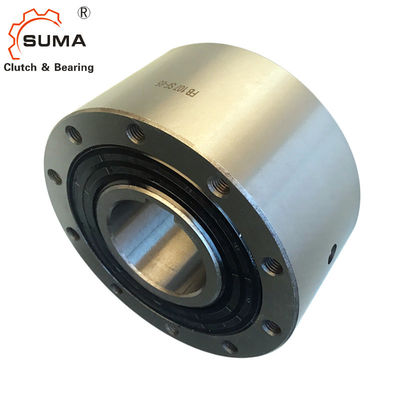
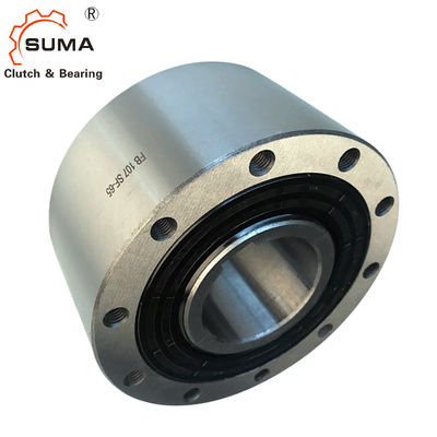
FB 82 GCr15 One Way Sprag 750 Nm Over Running Clutch
Features
Complete Freewheels FB are sealed sprag freewheels with ball bearings. They are supplied oil-filled and ready for installation.The freewheels FB are used as:
➧ Backstops
➧ Overrunning Clutches
➧ Indexing Freewheels
In addition to the standard type, four other types are available for extended service life and indexing accuracy.
Nominal torques up to 160 000 Nm.Bores up to 300 mm. Many standard bores are available.
Dimensions and Capacities
Fre ewh eel Size |
Ty pe |
Nom inal tor que |
M ring freew heels/ runs min-1 |
ax. speed ring freew heels/ runs min-1 |
Ty pe |
Nom inal tor que |
Max. speed ring freew heels/ runs min-1 |
Outer ring freew heels/ runs min-1 |
Ty pe |
Nom inal tor que |
Sprag lift- off at inn er ring spe ed min-1 |
Max. speed ring freew heels/ runs min-1 |
Ou ter ring dri ves min-1 |
Ty pe |
Nom inal tor que |
Sprag lift-off at outer ring speed min-1 |
Max. speed ring freew heels/ runs min-1 |
Inner ring driv es min-1 |
Ty pe |
Nom inal tor que |
FB 24 | CF | 45 | 4 800 | 5 500 | CFT | 45 | 4 800 | 5 500 | CFP | 19 | ||||||||||
FB 29 | CF | 80 | 3 500 | 4 000 | CFT | 80 | 3 500 | 4 000 | CFP | 31 | ||||||||||
FB 37 | SF | 200 | 2 500 | 2 600 | SFT | 200 | 2 500 | 2 600 | CZ | 110 | 850 | 3 000 | 340 | SFP | 120 | |||||
FB 44 | SF | 320 | 1 900 | 2 200 | SFT | 320 | 1 900 | 2 200 | DX | 130 | 860 | 1 900 | 344 | CZ | 180 | 800 | 2 600 | 320 | SFP | 180 |
FB 57 | SF | 630 | 1 400 | 1 750 | SFT | 630 | 1 400 | 1 750 | DX | 460 | 750 | 1 400 | 300 | LZ | 430 | 1 400 | 2 100 | 560 | SFP | 310 |
FB72 | SF | 1 250 | 1 120 | 1 600 | SFT | 1 250 | 1 120 | 1 600 | DX | 720 | 700 | 1 150 | 280 | LZ | 760 | 1 220 | 1 800 | 488 | SFP | 630 |
FB82 | SF | 1 800 | 1 025 | 1 450 | SFT | 1 800 | 1 025 | 1 450 | DX | 1 000 | 670 | 1 050 | 268 | SFZ | 1 700 | 1 450 | 1 600 | 580 | SFP | 750 |
FB 107 | SF | 2 500 | 880 | 1 250 | SFT | 2 500 | 880 | 1 250 | DX | 1 500 | 610 | 900 | 244 | SFZ | 2 500 | 1 300 | 1 350 | 520 | SFP | 1 250 |
FB 127 | SF | 5 000 | 800 | 1 150 | SFT | 5 000 | 800 | 1 150 | SX | 3 400 | 380 | 800 | 152 | SFZ | 5 000 | 1 200 | 1 200 | 480 | SFP | 3 100 |
FB 140 | SF | 10 000 | 750 | 1 100 | SFT | 10 000 | 750 | 1 100 | SX | 7 500 | 320 | 750 | 128 | SFZ | 10 000 | 950 | 1 150 | 380 | SFP | 6 300 |
FB 200 | SF | 20 000 | 630 | 900 | SFT | 20 000 | 630 | 900 | SX | 23 000 | 240 | 630 | 96 | SFZ | 20 000 | 680 | 900 | 272 | SFP | 12 500 |
FB 270 | SF | 40 000 | 510 | 750 | SFT | 40 000 | 510 | 750 | UX | 40 000 | 210 | 510 | 84 | SFZ | 37 500 | 600 | 750 | 240 | SFP | 25 000 |
FB 340 | SF | 80 000 | 460 | 630 | SFT | 80 000 | 460 | 630 | ||||||||||||
FB 440 | SF | 160 000 | 400 | 550 | SFT | 160 000 | 400 | 550 |
The maximum transmissible torque is 2 times the specified nominal torque. See page 14 for determination of selection torque.
Freewheel Size | mm | mm | Bore Standard mm |
red mm |
mm | max. mm | D mm | F mm |
G** | H mm | L mm |
T mm |
Z** |
Weight kg |
||
FB24 | 12 | 14* | 14* | 62 | 1,0 | M 5 | 8 | 50 | 51 | 3 | 0,9 | |||||
FB 29 | 15 | 17* | 17* | 68 | 1,0 | M 5 | 8 | 52 | 56 | 3 | 1,1 | |||||
FB37 | 14 | 16 | 18 | 20 | 22* | 22* | 75 | 0,5 | M 6 | 10 | 48 | 65 | 4 | 1,3 | ||
FB44 | 20 | 22 | 25* | 25* | 90 | 0,5 | M 6 | 10 | 50 | 75 | 6 | 1,9 | ||||
FB57 | 25 | 28 | 30 | 32* | 32* | 100 | 0,5 | M 8 | 12 | 65 | 88 | 6 | 2,8 | |||
FB72 | 35 | 38 | 40 | 42* | 42* | 125 | 1,0 | M 8 | 12 | 74 | 108 | 12 | 5,0 | |||
FB82 | 35 | 40 | 45 | 50* | 50* | 135 | 2,0 | M 10 | 16 | 75 | 115 | 12 | 5,8 | |||
FB107 | 50 | 55 | 60 | 65* | 65* | 170 | 2,5 | M 10 | 16 | 90 | 150 | 10 | 11,0 | |||
FB127 | 50 | 60 | 70 | 75* | 75* | 200 | 3,0 | M 12 | 18 | 112 | 180 | 12 | 19,0 | |||
FB140 | 65 | 75 | 80 | 90 | 95* | 250 | 5,0 | M 16 | 25 | 150 | 225 | 12 | 42,0 | |||
FB200 | 110 | 120 | 120 | 300 | 5,0 | M 16 | 25 | 160 | 270 | 16 | 62,0 | |||||
FB270 | 140 | 150 | 400 | 6,0 | M 20 | 30 | 212 | 360 | 18 | 150,0 | ||||||
FB340 | 180 | 240 | 500 | 7,5 | M 20 | 35 | 265 | 450 | 24 | 275,0 | ||||||
FB440 | 220 | 300 | 630 | 7,5 | M 30 | 40 | 315 | 560 | 24 | 510,0 |
Keyway according to DIN 6885, page 1 • Tolerance of keyway width JS10.
* Keyway according to DIN 6885, page 3 • Tolerance of keyway width JS10.
** Z = Number of tapped holes G on pitch circle T.
Mounting and Coupling
Mounting
The customer attachment part is on the exter-nal diameter D and then bolted on to the face.The tolerance of the shaft must be ISO h6 or j6 and the tolerance of the pilot diameter D of the attachment part must be ISO H7 or J7.
Example for ordering
Freewheel size FB 72, type with sprag lift-off Z and 38 mm bore: • FB 72 LZ, d = 38 mm
When ordering freewheel size FB 340 and FB440, please also specify the freewheeling direction of the inner ring when viewed in direction X: • counterclockwise free or • clockwise free
Pictures
Contact Us at Any Time