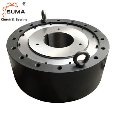
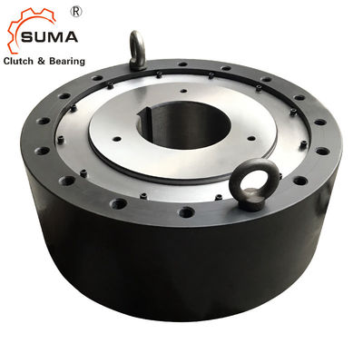
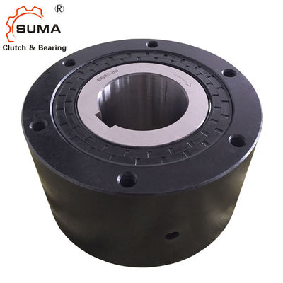
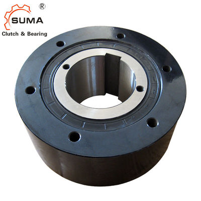
BS110 Belt Conveyor Overrunning Clutch Bearing 250RPM
Features
The BS series Cam Clutches are intended for applications where reverse rotation of the slow speed conveyor head shaft is to be prevented (backstopping).
1. For prevention of rotation in the reverse direction at slow speeds on conveyors or pumps.
2. Before installation, verify that the direction of rotation of the inner race of the BS Cam Clutch (shown by the arrow on the inner
race) is the same as the direction of rotation of the conveyor.
3. Securely install the torque arm to the BS Cam Clutch using bolts of strength 10.9 or higher. Make sure that the contact between
the surface of the torque arm and the side of the outer race is level and free of dust.
Dimensions and Capacities
Model |
Torque
Capacity
(Nm) |
Max.
Overrunning
(r/min)
Inner Race |
Drag
Torque
(Nm) |
A |
B |
C |
PCD
D |
E |
S |
H-M
Size× Pitch
× No.of Tapped Holes |
Weight
(kg)
|
| BS30 |
294 |
350 |
0.58 |
64 |
90 |
64 |
80 |
45 |
13 |
M 6 ×P1.0×4 |
2.1 |
| BS50 |
784 |
300 |
0.98 |
67 |
125 |
67 |
110 |
70 |
16 |
M 8 ×P1.25×4 |
4.0 |
| BS65 |
1570 |
340 |
3.92 |
90 |
160 |
85 |
140 |
90 |
20 |
M10 ×P1.5×6 |
11.5 |
| BS75 |
2450 |
300 |
5.88 |
90 |
170 |
85 |
150 |
100 |
20 |
M10 ×P1.5×6 |
13.1 |
| BS85 |
5880 |
300 |
7.84 |
115 |
210 |
110 |
185 |
115 |
30 |
M12 ×P1.75×6 |
24.7 |
| BS95 |
7840 |
250 |
9.8 |
115 |
230 |
110 |
200 |
130 |
30 |
M14 ×P2.0× 6 |
29.4 |
| BS110 |
10800 |
250 |
14.7 |
115 |
270 |
110 |
220 |
150 |
30 |
M16 ×P2.0× 6 |
34.2 |
| BS135 |
15700 |
200 |
19.6 |
135 |
320 |
130 |
280 |
180 |
30 |
M16 ×P2.0× 8 |
68 |
| Type |
Torque Capacity
(Nm)
|
Max. Overrunning
(r/min)
Inner race
|
Drag
Torque
(Nm)
|
A |
B |
C |
PCD
D
|
E |
S |
H-M
T.H.S.XP-Q'ty
|
G.F.H. (Size) |
Q. of G.
(kg)
|
| BS 160 |
24,500 |
100 |
34.3 |
135 |
360 |
130 |
315 |
220 |
40 |
M20xP2.5-10 |
PT 1/4 |
0.12 |
| BS 200 |
37,200 |
100 |
44.1 |
150 |
430 |
145 |
380 |
265 |
40 |
M22xP2.5- 8 |
PT 1/4 |
0.14 |
| BS 220 |
49,000 |
80 |
73.5 |
235 |
500 |
230 |
420 |
290 |
40 |
M20xP2.5-16 |
PT 1/4 |
0.8 |
| BS 250 |
88,200 |
50 |
93.1 |
295 |
600 |
290 |
530 |
330 |
50 |
M24xP3.0-16 |
PT 1/4 |
1.1 |
| BS 270 |
123,000 |
50 |
98 |
295 |
650 |
290 |
575 |
370 |
50 |
M24xP3.0-16 |
PT 1/4 |
1.2 |
| BS300 |
176,000 |
50 |
108 |
295 |
780 |
290 |
690 |
470 |
60 |
M30xP3.5-16 |
PT 1/4 |
1.3 |
| BS335 |
265,000 |
50 |
137 |
305 |
850 |
320 |
750 |
495 |
70 |
M36xP4.0-16 |
PT 1/4 |
1.4 |
| BS350 |
314,000 |
50 |
157 |
320 |
930 |
360 |
815 |
535 |
70 |
M36xP4.0-16 |
PT 1/4 |
1.5 |
| BS425 |
510,000 |
50 |
216 |
440 |
1,030 |
450 |
940 |
635 |
70 |
M36xP4.0-18 |
— |
Oil 6,000ml |
| BS450 |
686,000 |
50 |
245 |
450 |
1,090 |
480 |
990 |
645 |
80 |
M42xP4.5-18 |
— |
Oil 7,000ml |


Mounting and Coupling
4. Recommended shaft tolerance is h7 or h8.
5. When inserting the BS Cam Clutch on the shaft, apply pressure only on the inner race. Do not tap the inner race directly with a
hammer or exert any force upon the outer race, dust seal, or dust plate.
6. Always use a parallel key for installation onto the shaft and then fix the BS Cam Clutch to the shaft with the end plate. Never use
a tapered key.
7. When installing models above BS160 (grease lubricated types), place one of the four oil plugs in
The direct bottom location. This will allow for easy drainage of the grease for cleaning.
8. While the shaft is rotating, the end of the torque arm will swing to some extent in the direction of rotation. Support the torque arm
end only in the direction of rotation, but be sure to allow it a certain amount of free swing. If the torque arm end is fixed securely
(see installation diagram), the inside of the clutch becomes twisted, and this can result in damage to the components.
9. For models BS30 to BS200, a single torque arm on one side is sufficient, but for models 220 to BS450, use two torque arms, one
on each side. Install the torque arms evenly so the force is transmitted through the center of the clutch.
10. Torque arms for the BS Cam Clutch are standardized.
Pictures


 Your message must be between 20-3,000 characters!
 Please check your E-mail!
  Your message must be between 20-3,000 characters!
 Please check your E-mail!


