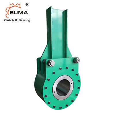
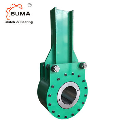
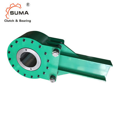
BC12MA BC18MA High Torque Transmission Sprag Type
One Way Clutch Bearing
Technical Datas
BC backstops are completely mechanical, automatic operating units, incorporating a time proven basic operating principle, to provide greater safety and longer life with minimum maintenance requirements. Seventeen standard sizes are available up to 1,200,000 pound-feet of torque.
During freewheeling, (normal operation), the cam and roller assembly rotate with the headshaft as shown by the arrows in Illustration 2. The outer race is secured to stationary coverplates and "I" Beam Torque arm.
An oil film wedges and separates the rollers from the outer race. This moves the rollers a few thousandths of an inch imparting relative angular motion between the roller cage and cam.
This slight movement of the rollers into the deeper cam zones, with a clean lubricant film wedged between rollers and outer race, permits freewheeling without metal to metal contact.
Dimensions and Capacities
Backstop Size |
Torque N-m |
Rated Torque lb. ft. |
Max RPM |
Load "L" Kgs. |
Load "L" lbs. |
Max.* Bore mm | Max.* Bore in. |
Max.* Bore Keyway mm |
Max.* Bore Keyway in. |
Ship Weight Kgs. | Ship Weight lbs. |
3MA | 4067 | 3,000 | 300 | 510 | 1,120 | 75 | 2.94 | 20 x 4.9 | .75 x .25 | 46 | 100 |
6MA | 8135 | 6,000 | 250 | 920 | 2,000 | 95 | 3.69 | 25 x 5.4 | .88 x .31 | 69 | 150 |
12MA | 16270 | 12,000 | 210 | 1325 | 2,880 | 115 | 4.50 | 32 x 7.4 | 1.00 x .38 | 100 | 220 |
18MA | 24405 | 18,000 | 180 | 1776 | 3,860 | 140 | 5.44 | 36 x 8.4 | 1.25 x .44 | 152 | 330 |
Backstop Size | A | B | C | D | E | F | G | |||||||
mm | in. | mm | in. | mm | in. | mm | in. | mm | in. | mm | in. | mm | in. | |
3MA | 210 | 8.25 | 143 | 5.62 | 146 | 5.75 | 64 | 2.50 | 76 | 3 | 813 | 32 | 105 | 4.12 |
6MA | 248 | 9.75 | 165 | 6.50 | 169 | 6.62 | 70 | 2.75 | 102 | 4 | 914 | 36 | 124 | 4.87 |
12MA | 292 | 11.50 | 203 | 8.00 | 178 | 7.00 | 83 | 3.25 | 127 | 6 | 1270 | 50 | 146 | 5.75 |
18MA | 343 | 13.50 | 235 | 9.25 | 189 | 7.44 | 92 | 3.62 | 152 | 6 | 1422 | 56 | 168 | 6.6 |
Backstop Size |
Torque N-m |
Rated Torque lb. ft. |
Max RPM |
Load "L" Kgs |
Load "L" lbs. |
Max.* Bore mm | Max.* Bore in. | Max.* Bore Keyway mm |
Max.* Bore Keyway in. |
Ship Weight Kgs. | Ship Weight lbs. |
27MA | 36607 | 27,000 | 150 | 2259 | 4,910 | 165 | 6.50 | 40 x 9.4 | 1.50 x .50 | 207 | 450 |
45MA | 61012 | 45,000 | 135 | 3450 | 7,500 | 180 | 7 | 45 x 10.4 | 1.75 x .56 | 276 | 600 |
63MA | 85417 | 63,000 | 120 | 4462 | 9,700 | 205 | 8 | 50 x 11.4 | 2.00 x .69 | 381 | 830 |
90MA | 122024 | 90,000 | 105 | 6072 | 13,200 | 235 | 9 | 56 x 12.4 | 2.50 x .75 | 520 | 1,130 |
135MA | 183035 | 135,000 | 90 | 8464 | 18,400 | 265 | 10 | 63 x 12.4 | 2.50 x .87 | 690 | 1,500 |
180MA | 244047 | 180,000 | 80 | 10580 | 23,000 | 300 | 11.75 | 70 x 14.4 | 3.00 x 1.00 | 966 | 2,100 |
Backstop Size | A | B | C | D | E | F | G | |||||||
mm | in. | mm | in. | mm | in. | mm | in. | mm | in. | mm | in. | mm | in. | |
27MA | 384 | 15.12 | 254 | 10.00 | 222 | 8.75 | 98 | 3.87 | 178 | 7 | 1676 | 66 | 191 | 7.50 |
45MA | 445 | 17.50 | 289 | 11.37 | 235 | 9.25 | 105 | 4.12 | 203 | 8 | 1829 | 72 | 216 | 8.50 |
63MA | 498 | 19.62 | 311 | 12.25 | 244 | 9.62 | 127 | 5.00 | 254 | 10 | 1981 | 78 | 244 | 9.62 |
90MA | 584 | 25.75 | 362 | 14.25 | 276 | 10.87 | 140 | 5.50 | 305 | 12 | 2083 | 82 | 270 | 10.62 |
135MA | 654 | 30.37 | 406 | 16.00 | 314 | 12.37 | 143 | 5.62 | 381 | 15 | 2235 | 88 | 308 | 12.12 |
180MA | 772 | 34.50 | 419 | 16.50 | 330 | 13.00 | 159 | 6.25 | 457 | 18 | 2388 | 94 | 349 | 13.75 |
Mounting and Coupling
When the conveyor decelerates and the cam subsequently comes to rest, the spring actuated roller cage, Illustration 1, has already positioned the rollers into the contact zone. All rollers have been positively guided to engage uniformly and maintain their relative positions accurately to assure uniform load distribution. The rollers then engage in compression between the precision ground, hardened cam plane surfaces and the inside diameter of the outer race. Relative motion between the cam and outer race is not required to engage rollers. When the backstop is in the "engaged" or "backstopping" condition, the cam, rollers, and outer race are relatively stationary and therefore, not subject to wear if used within normal tabulated rating.
Mounting Details
Backstops are furnished with a clearance fit between the bore and shaft for easy field installations. The key should be a “drive tight” fit on the sides only. As a result a method of axial shaft retention is required for all backstops. The preferred method of accomplishing this is with the use of set collars which can be furnished by SUMA upon request.
Pictures
Contact Us at Any Time